Important DC Advisory
Do NOT use cheaper "train-set"-type controllers with any of your Rapido locomotives. Several models of controller are notorious for voltage spikes and they WILL destroy your locomotive. There is no “if” about it. We will try to help you if we have the parts, but we are not responsible for locomotive damage due to voltage spikes in your power supply. As well, we will not repair any Rapido locomotive damaged by any "train-set"-type DC controller unless you have retired the controller. Otherwise the damage will likely reoccur. “Train-set”-type DC controllers should not be used with any modern model locomotives.
General Problems and Inquiries
If your model arrives with damage or there is any other issue, the best thing to do is to call our support team. They take care of all of our warranty repairs and they are all swell guys. The toll-free number is 1-855-LRC-6917 (1-855-572-6917) (outside North America, + 1 905-474-3314 or 905-474-3324).
Function Issues on Digitrax Systems
If you operate with a Digitrax DCC system and your DCC loco does not seem to be responding as it should, please try the fix described below before contacting us. It may save you some time and aggravation! Apparently, some Digitrax systems store the address of every single loco that they’ve ever used on them, and regardless of whether the loco was dispatched or not. Once this memory fills up, any new locos that attempt to be used by that system exhibit very unusual behavior including non-working functions and odd responses. The solution to this is easy. All you need to do is clear the memory in your system. This is done by clearing slot #36; see the instructions below. Once you’ve done this, you’ll likely find that your loco operates exactly as you expected it should. General Instructions for Closing Command Station Option Switches (for specific instructions for your command station and throttle, see the instruction manual for your equipment):
- On the command station, set the MODE toggle switch to the OP (center) position.
- Using your throttle go into Switch Mode
- Enter the Option Switch number you wish to change (in this case 36).
- Press the “c” key on the throttle.
- You will hear a beep.
- On the command station move the MODE toggle down to SLEEP then back up to RUN.
- Using your throttle, turn Track Status back on.
For more information, see this page from Digitrax’s web site.
EP-5 Decoder Update
The EP-5 Decoder Project has been updated to add a Function - F27 “Third Rail Mode” This function is designed to retract both Pantographs to simulate running using Third Rail power. F27 only works with F8 (Sound) = ON
The Pantograph functions work in the following manner:
- F8 = ON, F27 = OFF - the rear pantograph is up (depending on direction), and cannot be lowered with F13/14. The front one can be raised/lowered independently.
- F8 = ON, F27 = ON - Both pans are down, and F13/14 both work independently.
- F8 = OFF - F13/14 both work independently.
This update is a full re-write of the EP-5 sound project, not a simple “change some CV’s”. You will need to have access to an ESU LokProgrammer to be able to do this update. You will have had to supply Rapido Customer Service (Warranty) with the Serial Number of the decoder you wish to update. The Project file will only write to the decoder with the correct serial number.
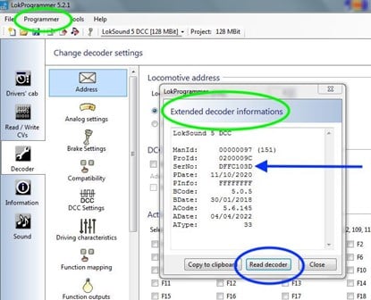
To find the decoder serial number using the LokProgrammer, Click on “Programmer” and then from the drop down list, click on “Extended Decoder Informations”. The “Extended Decoder Informations” window will open – Click the “Read decoder” button. The decoder information will appear – the Blue Arrow indicates the serial number.
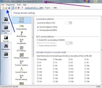
The new file is approximately 26 Mb and will need to loaded to a drive that LokProgrammer can access.
Open the new file by clicking on file folder icon (Blue arrow), choose and open the new file. When opened the file name will appear at the top of the window (Purple arrow).
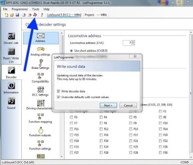
Next, click the Write Sound Data icon to open the dialogue screen (Blue arrow). Make sure the “Write decoder data” and “Overwrite defaults with current values” boxes are ticked, then click the “Next” button.
The update will take about 25-30 minutes to complete.
Installing the Locomotive Pilot Steps
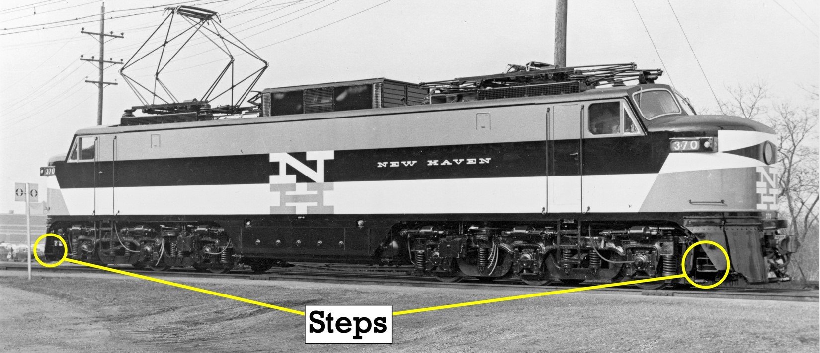
The New Haven’s EP-5 “Jet” locomotives were delivered from General Electric with a pair of single steps mounted to the rear of the curved pilots at each end of the locomotive. These steps allowed a brakeman to ride on either side of the EP-5 nose during switching moves.
The Rapido HO scale model of the EP-5 includes these steps, but they were not installed at the factory for a very good reason; if installed, they prevent the shell from coming off the chassis without removing the steps first. Therefore…
DO NOT USE A PERMANENT ADHESIVE TO ATTACH THE PILOT STEPS!
Inside the box of every Rapido EP-5, one should find a small plastic bag with four rectangular pieces of hollow black plastic in it. These pieces are the pilot steps that mount to the underside of each pilot. There are two left and two right steps: a pair for each end of the EP-5.
To install these parts, follow these instructions:
1). Find the parts in a bag in the box; you should have two lefts and two rights as seen here. The open side of the step is up in the photo.

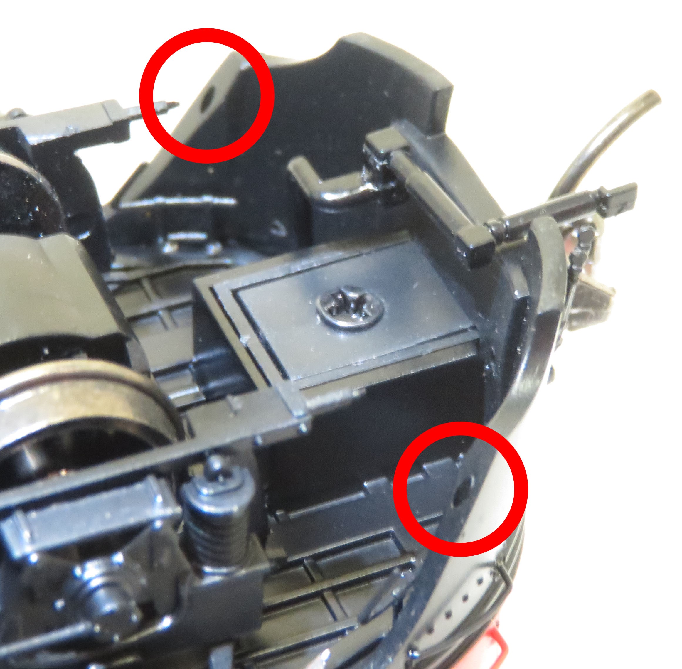
2). Carefully turn your EP-5 over on a piece of foam and look at the edges of each pilot. You should find two holes cast into the pilot’s edge, shown here circled in red.
3). The steps can be identified left and right by looking at the open side of the step and the mounting peg’s location. The open side of the step box should always face outward on the model and the mounting peg should be closest to the nearby coupler.
4). We recommend white glue (like Elmer’s) to attach the steps to the model. You could use another kind of adhesive like Hob-E-Tac, Kristal Klear, Liquitape, etc., if it’s a temporary adhesive. DO NOT USE Superglue, CA, or any plastic solvent cement.
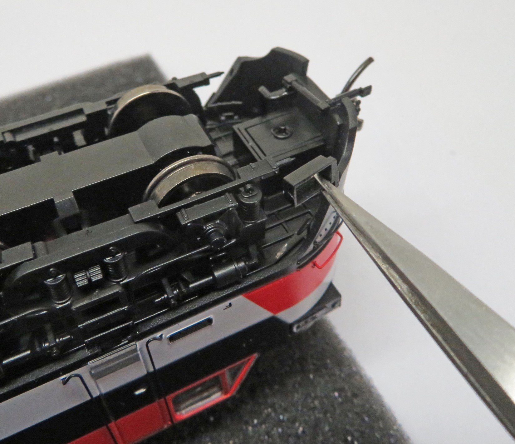
Make a little puddle of glue on a disposable surface. Use tweezers to grab the open side of a step and dip the mounting peg into the glue to get a tiny amount of adhesive on the peg. Insert the step’s mounting peg into the hole on the bottom edge of the pilot as shown in the photo. Push it in all the way; it should go in easily.
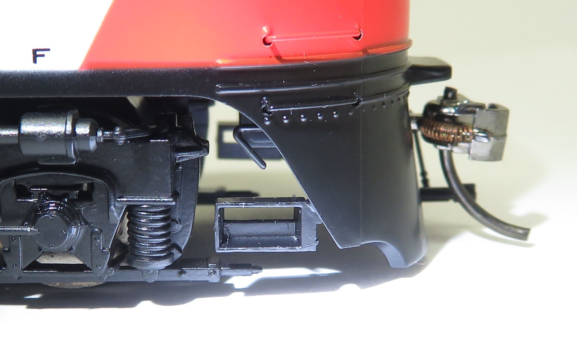
5). Before the glue sets, orientate each step so it is parallel and in line with the track as seen in the red ovals in the photo. Note how the steps are now out over the chassis, which prevents the shell from being removed with the steps installed.

6). The finished installation should look like this:
7). If you need to remove the shell to gain interior access to the EP-5 after the steps have been applied, simply twist gently on each step to break the (hopefully) weak glue bond. With white glue, it won’t take much force. If you used a permanent adhesive and you want to remove the shell, we’re sorry but your steps are going to get broken (we did warn you!).
You can also download these instructions as a PDF document here.
EP-5 Operating Manuals and Diagrams
To view the files, you will need Adobe Reader. Click below to get it.